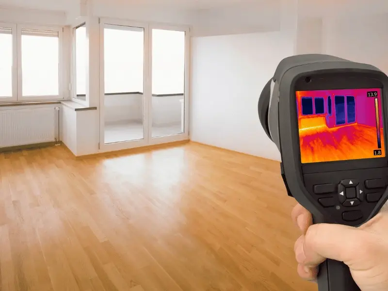
Quick Answer: An infrared camera for water leak detection finds slab leaks by capturing temperature variations on floors and walls caused by moisture cooling or heating nearby surfaces. It doesn’t “see” water, it maps infrared radiation and reveals thermal images (thermograms) where leaks change heat flow, often through evaporative cooling or delayed cooling after heat exposure. For best results, create stronger temperature contrast, scan at the correct angle to avoid reflection, then verify with a pinless moisture meter, pressure testing, or a water meter test. Used correctly, this non-destructive method can narrow a leak zone fast and reduce unnecessary concrete cutting.
Fast Warning Signs You Can Spot During a Walkthrough
You can suspect a slab leak before scanning when the building shows consistent moisture or heat anomalies.
Even before you pick up the thermal imaging camera, watch for signs of slab leaks that show up repeatedly in the same area especially along bathrooms, break rooms, mechanical spaces, and hallways built on a concrete slab.
Quick On-Site Clues
- Persistent dampness or dark staining on a concrete floor
- A “cold patch” or warm strip that doesn’t match HVAC patterns
- Musty smell or early mold growth indicators near baseboards
- Unexplained moisture near walls or door thresholds
- Small cracks in concrete floor or foundation that coincide with dampness
- Water sounds that seem to come from beneath the slab
What Infrared Thermography Actually Detects (It’s Not “Water Vision”)
An infrared camera for water leak detection detects surface temperature patterns not liquid water itself.
This method is called infrared thermography and it works by measuring infrared energy emitted from surfaces. The camera produces thermograms (thermal images) that highlight temperature variations. Leaks under slabs often reveal themselves because wet materials behave differently than dry materials especially during heating/cooling cycles.
A key concept is emissivity / infrared radiation: different materials (tile, concrete, carpet, vinyl) emit heat differently, so you must interpret patterns carefully.
Why Slab Leaks Show Up in Thermal Images
Slab leaks often create visible patterns in thermal scans because water changes heat transfer.
Here’s what’s happening in plain language:
- Water under or within porous materials can cool areas as it evaporates (evaporation / evaporative cooling).
- Water trapped beneath surfaces can retain heat longer than surrounding dry materials (related to radiational cooling timing).
- The result is a detectable pattern of temperature contrast that a thermal camera can map.
To avoid misdiagnosis, you also need to consider the ambient temperature and airflow from vents. A cold air draft can mimic a leak in some situations.
Common Sources of Heat/Cold Patterns That Aren’t Slab Leaks
Not every “hot spot” is a pipe leak. Sometimes thermal anomalies come from other systems.
Before you commit to a slab-leak theory, account for common sources of water leaks and non-leak thermal issues that can look similar:
- HVAC duct leaks or uneven distribution
- Missing insulation behind walls
- Sun-heated areas near glass storefronts
- Electrical hotspots in panels or conduits
- Exterior rain intrusion traveling along framing
If you also suspect overhead moisture issues, remember that finding roof leaks with thermal imaging is a different workflow than slab scanning (different timing and conditions).
Tools You Need for Reliable Infrared Leak Detection
Thermal scanning works best when paired with basic verification tools.
The camera matters, but the workflow matters more. Competitors mention tools yet many skip how to combine them into a repeatable field process.
What to Look for in a Thermal Imaging Camera
Choose a camera with:
- high resolution imaging for sharper pattern definition
- strong thermal sensitivity (to detect subtle differences)
- ability to adjust level/span for clearer contrast
- a stable focus system for consistent scans
Some technicians reference flir water leak detection because FLIR cameras are common in this workflow, but the principles apply across brands.
Companion Tools That Increase Accuracy
- pinless moisture meter (surface moisture verification)
- hygrometers (humidity measurement for evaporative interpretation)
- tape measure for mapping patterns
- visual camera for “before/after” documentation
Best Scan Setup: Temperature, Timing, and Delta T
The success of infrared cameras for water leak detection depends on how much temperature difference exists.
Delta T-Your Best Friend
Delta T (temperature difference) is the measurable gap between the suspect area and surrounding materials. Bigger Delta T usually means easier interpretation.
Tip (practical): If you’re getting flat, low-contrast images, don’t assume “no leak.” Often you simply don’t have enough Delta T.
How to Create Better Contrast Safely
- Run cold water, then stop and scan for cooling patterns.
- In some environments, changing HVAC operation can sharpen patterns.
- For radiant systems, a heat/cool cycle can reveal line paths more clearly.
Angle Matters: Avoid Reflection and False Readings
Scan angle is a common reason people fail with thermal cameras.
Concrete and tile can reflect infrared energy like a mirror. If your angle is wrong, you’ll capture reflection of your own heat signature, lights, or hot equipment.
Recommended scan angle (60–90 degrees) to the surface helps reduce reflections and gives more reliable thermograms.
Quick fix (field trick): If you see a suspicious “blob,” move laterally and re-scan. Reflections shift; true subsurface patterns remain anchored.
Step-by-Step: How Infrared Camera for Water Leak Detection Finds Slab Leaks
This is the repeatable process that turns thermal images into actionable leak zones.
Thermal Scanning Workflow
- Start with a visual inspection: stains, dampness, odor, and crack patterns.
- Note ambient temperature, HVAC vents, and sun exposure.
- Scan in a grid pattern and capture consistent thermograms.
- Adjust level/span to increase temperature contrast without “over-coloring.”
- Re-scan from multiple angles to rule out reflection artifacts.
- Mark suspect boundaries on the floor and photograph both thermal + visible.
- Verify with a pinless moisture meter and document readings.
This process is the backbone of thermal imaging water leak detection and works best when you keep your scan systematic.
Moisture Verification: Don’t Stop at Thermal Images
Thermal images are strong clues, but verification protects you from miscalls.
A pinless moisture meter can confirm moisture near the surface. Remember a limitation: pinless meters typically read shallow depth (often around an inch), so they won’t “see” deep water the way thermography can. Still, it’s valuable for confirming affected zones.
When moisture readings don’t match thermal patterns, re-check for airflow, insulation gaps, or surface wetting from cleaning.
Combine Infrared With Pressure and Meter Testing for Proof
Thermal scanning shows patterns; tests confirm loss.
Pressure Testing for Confirmation
Pressure testing (pressure drop confirmation) helps validate whether a supply line is leaking. You pressurize and monitor for drop over time.
Water Meter Test for “Leak vs. Usage”
A water meter test (meter movement when off) is simple: shut off all water use and watch if the meter still moves. Movement indicates flow somewhere, often a hidden leak.
Tip: Thermal finds the “where.” Meter/pressure tests confirm the “is it real?”
Leak Detection in Concrete Slab: What Patterns Look Like
Thermal patterns tend to follow physics and pipe routing.
In leak detection in concrete slab, common thermogram patterns include:
- elongated “river-like” cool zones (often moisture traveling)
- oval-shaped cool spots that widen over time
- linear warm traces near hot lines
A thermal camera water leak signature usually has soft edges and spreads along porous pathways, unlike sharp HVAC draft lines.
Special Case: In-Floor Radiant Heating Systems
Radiant heating adds both opportunities and pitfalls in thermal interpretation.
Radiant Components You Might See on Thermograms
In buildings with in-floor radiant heating, scans may reveal:
- radiant heating coils paths
- the manifold location
- PEX supply and return lines
- temperature differences tied to flow
Many systems reference supply/return temperature rise and the boiler performance. If there’s a major leak, return temperature can fall, and thermograms will show abnormal patterns.
Radiant Scan Quick Method
- Start at the manifold area and document baseline temps.
- Measure supply and return to confirm expected rise.
- Run a short heat cycle, then scan for uneven cooling/heating lines.
- Flag sections where the line abruptly “disappears” or cools abnormally.
Thermal Imaging Through Concrete: What’s Realistic (and what isn’t)
Thermal imaging through concrete is not x-ray vision, it’s surface pattern interpretation.
Concrete is dense, and depth matters. If a pipe is deep and the Delta T is small, the surface effect may be faint. Also, wet insulation or surface wetting can confuse readings.
Fact-based guidance: On many surveys, meaningful thermal differences can range from a couple degrees Fahrenheit to much larger swings depending on conditions. That’s why timing and contrast creation matter so much.
When Infrared Works Best (and When It Struggles)
Infrared succeeds when conditions support clear thermal differences.
Best vs. Worst Conditions
- Best: stable HVAC, dry surface, strong Delta T, low reflections, repeatable patterns
- Worst: wet surface on top of the slab, high glare/reflection, strong sunlight heating everything evenly, heavy airflow drafts, or very small temperature differences
If you scan at the wrong time or on a wet surface, thermograms can become inconclusive.
Non-Destructive vs. Destructive: How Infrared Saves Money
Infrared is popular because it’s non-destructive / non-invasive testing.
Used correctly, it:
- reduces unnecessary concrete cutting
- narrows the work zone to the most likely leak corridor
- speeds diagnosis and documentation for property teams
Once a zone is identified, a qualified team can decide the least disruptive next step.
When you need that next step, experienced commercial plumbing technicians can combine thermal findings with acoustic and pressure diagnostics.
Advanced Pairing Tools (Acoustic + Electronic) for Hard Cases
When thermography is inconclusive, pairing tools boosts success.
- acoustic listening devices help detect sound signatures under slabs.
- ground microphones / vibration sensing can trace vibration patterns.
- Electronic leak detection tools can refine location further.
Thermal often identifies a “wet area.” Acoustic/electronic tools narrow to “this line segment.”
Safety and Risk Notes for Commercial Properties
Slab leaks can create hazards beyond water damage:
- slip-and-fall risk on polished floors
- moisture near electrical systems
- microbial growth concerns
If you have active saturation or rapid spread, bring in emergency water damage experts early so drying begins while diagnostics continue.
Quick Fixes That Help Before the Full Repair Plan
These aren’t permanent repairs, but they reduce damage while you diagnose.
Quick fixes (practical and safe):
- Limit water use on the suspected branch if possible.
- Dry visible moisture quickly to prevent spread and odor.
- Keep a humidity log using hygrometers to track conditions.
- Document thermograms + photos for consistent comparison.
If you’re coordinating vendors, aim to work with the best plumbing company that can interpret thermograms correctly and confirm with meter/pressure proof.
Decision Tables: What to Do With What You See
Use these tables to interpret patterns and next steps.
Thermal Patterns and What they Often Mean
Thermal Pattern | Likely Cause | Best Next Check |
Cool “river” spreading zone | Moisture intrusion migration | Pinless meter + humidity log |
Linear warm trace | Hot line proximity or leak | Verify with pressure testing |
Patchy cool area near vent | HVAC draft / insulation issue | Airflow check + re-scan angle |
Large uniform warm floor | Sun load / radiant heat | Time-of-day re-scan |
Confirmation Methods and What they Prove
Method | What it Confirms | Notes |
Water meter test | Flow exists when “off” | Great for yes/no leak confirmation |
Pressure testing | System can’t hold pressure | Doesn’t pinpoint alone |
Pinless moisture meter | Moisture near surface | Depth-limited but useful |
Acoustic devices | Leak sound/vibration | Strong in quiet conditions |
Call DR HOUSE INC for Targeted Leak Diagnostics
When you need fast, low-disruption answers from thermal imaging plus verification testing, DR HOUSE INC can help you move from “suspected leak” to “confirmed location” with clear documentation.
Company: DR HOUSE INC
Call: 8587037536
FAQs About Infrared Camera Water Leak Detection
Does an infrared camera for water leak detection see water directly?
No, an infrared camera for water leak detection reads temperature patterns caused by moisture and heat transfer, then displays them as thermograms. You confirm with moisture and pressure checks.
How accurate is thermal imaging for slab leaks?
It’s highly effective when Delta T is strong, surfaces are dry, and scan angles reduce reflection. Accuracy improves further when paired with a moisture meter and meter/pressure testing.
What causes false positives in thermal images?
Reflections, HVAC drafts, missing insulation, sun load, and wet surfaces on top of the slab can create misleading thermograms. Re-scanning from multiple angles helps.
Can thermal imaging locate other leaks besides slabs?
Yes, thermal imaging can also highlight moisture intrusion in walls and ceilings, and it’s commonly used for roof investigations, plumbing chases, and envelope leaks (under the right conditions).
What should I do if I confirm a leak?
Document thermograms, confirm with meter/pressure tests, and isolate the suspected branch to reduce damage. Then plan a targeted repair approach based on verified location.